CATHODE RAY OSCILLOSCOPE (What is CRO , its working principle and structure)?
CATHODE RAY OSCILLOSCOPE

INTRODUCTION
— The
cathode-ray oscilloscope (CRO) is for
measurements , and analysis of waveforms
— CRO is generally an
x-y plotter; on a single screen it can
display different signals applied to different channels.
— A
moving luminous spot over the screen displays the signal.
— The
central unit of the oscilloscope is the cathode-ray tube (CRT), and the
remaining part of the CRO consists of the circuitry required to operate the
cathode-ray tube.
Block
diagram of a cathode-ray oscilloscope:


COMPONENTS OF THE CATHODE-RAY OSCILLOSCOPE
The CRO consists of the following:
• ( i) CRT
• ( ii)
Vertical amplifier
• ( iii)
Delay line
• ( iv)
Horizontal amplifier
• (v)
Time-base generator
• ( vi)
Triggering circuit
• (vii) Power
supply
FUNCTIONAL UNITS

a) Electron Gun
b) Evacuated Tube
c) Deflecting System
d) Time Base
e) Trigger Circuit
ELECTRON GUN

Electron Gun

a)
Heating Filament
b)
Cathode
c)
Grid
d) Electron
lens
Fluorescent Screen:
— Phosphor is used as screen
material on the inner surface of a CRT. Phosphor absorbs the energy of the
incident electrons. The spot of light is produced on the screen where the
electron beam hits.
— The bombarding electrons striking
the screen, release secondary emission electrons. These electrons are collected
or trapped by an aqueous solution of graphite.
— Collection of the secondary
electrons is necessary to keep the screen in a state of electrical equilibrium.
— The type of phosphor used,
determines the color of the light spot. The brightest available phosphor
isotope, P31, produces yellow–green light with relative luminance of 99.99%.
Electron Gun
•
In the electron gun, electrons are emitted, converted into a sharp beam
and focused upon the fluorescent screen.
•
The electron gun consists of an indirectly heated cathode, a control
grid, an accelerating electrode and a focusing anode.
•
The electrodes are connected to the base pins. The cathode emitting the
electrons is surrounded by a control grid with a fine hole at its centre.
•
The accelerated electron beam passes through the fine hole.
•
The negative voltage at the control grid controls the flow of electrons
in the electron beam, and consequently, the brightness of the spot on the CRO
screen is controlled.
EVACUATED TUBE
•
Vacuum space
•
Screen
•
Graphite inner wall
DEFLECTING SYSTEM
•
X-plates

•
Y-plates
•
X and Y
Deflection Amplifiers
•
X-shift Control
•
Y-shift Control
•
Sensitivity Control
DEFLECTION SYSTEM
•
Electrostatic deflecting system
consists of a pair of horizontal and vertical deflecting plates.
•
Let us consider two parallel vertical deflecting plates P1 and P2. The beam is focused at point O on
the screen in the absence of a deflecting plate voltage.
•
If a positive voltage is applied
to plate P1 with respect to plate P2, the
negatively charged electrons are attracted towards the positive plate P1, and these electrons will come to focus
at point Y1 on the fluorescent screen.
The
deflection is proportional to the deflecting voltage between
the plates. If the polarity of the deflecting voltage is reversed, the spot
appears at the point Y2, as shown in Fig.
(a).

•
To deflect the beam horizontally, an alternating
voltage is applied to the horizontal deflecting plates and the spot on the
screen horizontally, as shown in Fig. 14-3( b ).
•
The electrons will focus at point X2. By changing the polarity of voltage, the beam will focus at point
X1. Thus, the horizontal movement is controlled along X1OX2 line.

TIME BASE :
•
Sawtooth potential difference
•
Time period control

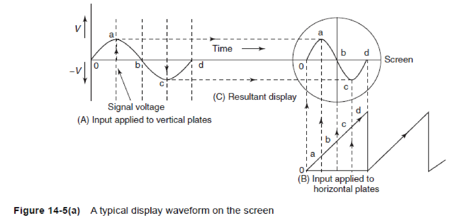
Display waveform on the screen:
•
Figure shows a sine wave applied to vertical deflecting plates and a
repetitive ramp or saw-tooth applied to the horizontal plates.
•
The ramp waveform at the horizontal plates causes the electron beam to
be deflected horizontally across the screen.
•
If the waveforms are perfectly synchronized then the exact sine wave
applied to the vertical display appears on the CRO display screen.
Triangular waveform:
Similarly the display of the triangular waveform
is as shown in Figure.

TIME-BASE GENERATORS:
•
The CRO is used to display a waveform that varies as a
function of time.
•
As the beam velocity is a function of the deflecting
voltage, the deflecting voltage must increase linearly with time.
•
A voltage with such characteristics is called a ramp
voltage. If the voltage decreases rapidly to zero—with the waveform repeatedly
produced, as shown in Fig. 14-6—we observe a pattern which is generally called
a saw-tooth waveform.
•
The time taken to return to its initial value is known
as flyback or return time.

Trigger Circuit
•
Maintain a stable trace
•
Trig level control
•
Trigger time base
•
automatic triggering
POINTS TO REMEMBER:
•
1 . CRO is used to study waveforms.
•
2 . CRT is the main component of a CRO.
•
3. Prosperous P31 is used for the fluorescent screen
of a CRO.
•
4 . A CRO has the following components :
– ( a)
Electron gun
– ( b)
Deflecting system
– ( c)
Florescent screen
•
5. Lissajous figures are used to measure frequency and
phase of the waves under study.
•
6. A time-base generator produces saw-tooth voltage.
•
7 . An oscilloscope amplifier is used to give input
signal


Comments
Post a Comment